
In a seawater reverse osmosis (SWRO) desalination plant, the membrane is the component that actually separates salt from water. Everything else—intake, pretreatment, high-pressure pumps, energy recovery devices, post-treatment—exists so that the membranes can operate under the best possible conditions. For this reason, choosing the right Desalination Membranes is important: it dictates product water quality, energy consumption, cleaning frequency, replacement costs, and, in the case of a containerized desalination plant, even how many pressure vessels will fit inside the container.
In this article, based on I’mWATER’s experience designing and manufacturing compact and containerized desalination plants, we review what a seawater membrane is, what variants exist, how to correctly read a technical datasheet, and what criteria we apply to select the best option for each project.
Why Seawater Requires Specific Membranes
Seawater contains, on average, around 35,000 mg/L of total dissolved solids, although this figure varies greatly depending on the region: the Atlantic is around 36,000 mg/L, the Mediterranean exceeds 38,000 mg/L, and seas like the Red Sea or the Persian Gulf can reach 41,000–45,000 mg/L. This salinity translates to an osmotic pressure of about 27 bar for 35 g/L water, which is the minimum pressure that must be overcome to start producing fresh water.
However, osmotic pressure is not constant throughout the system. As water moves through the elements and permeate is extracted, the concentrate becomes more concentrated. At a 45% recovery rate, the brine exiting the final element contains around 64 g/L with an osmotic pressure close to 50 bar. This is why SWRO plants typically operate between 55 and 70 bar, and why seawater membranes are built to withstand pressures up to 82–83 bar (1,200 psi).
A brackish water reverse osmosis (BWRO) membrane may look identical on the outside—same diameter, same length—but its flat sheet, feed spacers, and outer shell are designed for operating pressures of 10–40 bar and lower salt rejection levels. Installing brackish elements in a seawater system leads to membrane compaction, loss of rejection, and, in the worst-case scenario, mechanical damage. This is the first rule: for seawater, always use specific SWRO elements.
Inside a Seawater Reverse Osmosis Membrane
Virtually all commercial SWRO membranes are made of thin-film composite (TFC) polyamide in a spiral-wound configuration. The sheet has three layers:
- Active polyamide layer, barely 0.1–0.2 µm thick, which actually performs the salt rejection.
- Microporous polysulfone support, which provides structural strength to the active layer.
- Polyester fabric backing, which provides mechanical strength to the entire sheet.
Several membrane “leafs” are folded into envelopes wrapped around a central perforated tube, separated by a feed spacer (through which seawater flows) and a permeate carrier (through which product water travels spirally toward the central tube). The entire assembly is wrapped in a fiberglass casing and fitted with an anti-telescoping device at each end.
Other technologies exist—hollow fiber, cellulose acetate, thin-film nanocomposite (TFN) membranes—but today they represent a minority or are reserved for niche applications. For a containerized seawater plant, the market standard is the polyamide spiral-wound element.
Formats: 2540, 4040, and 8040
The element nomenclature indicates diameter and length in inches: an 8040 measures 8″ in diameter by 40″ long (approximately 200 × 1,016 mm). The three standard formats in desalination are:
| Format | Typical Active Area | Common Usage |
|---|---|---|
| 2540 | 2.5–2.8 m² | Very small equipment, boats, laboratory (up to ~10–20 m³/day) |
| 4040 | 7–8 m² | Small compact plants (guideline 20–150 m³/day) |
| 8040 | 37 m² (400 ft²) or 41 m² (440 ft²) | Medium and large plants, starting from ~150–200 m³/day |
In I’mWATER containerized plants starting around 100–200 m³/day, we almost exclusively work with 8″ elements. Their area-to-volume ratio is far superior, the cost per cubic meter produced is lower, and spare parts are readily available in almost any country—a critical factor when a plant is installed on a Caribbean island, at an industrial port, or at an isolated mining site.
Within the 8040 format, it is worth distinguishing between 400 ft² and 440 ft² elements. Higher-area elements use thinner feed spacers (typically 28 mil vs. 34 mil): they produce more water per element, but are slightly more sensitive to fouling. We will explore how this choice influences container design later on.
SWRO Membrane Families: Not All Target the Same Goals
All major manufacturers offer several “families” of seawater elements. Commercial names vary, but the underlying logic remains constant: balancing permeability (how much water passes per unit of pressure) and selectivity (how much salt and boron are rejected). Enhancing one usually compromises the other.
High Rejection
Nominal rejections of 99.80–99.85% and superior boron rejection. They require slightly higher pressure. They are the natural choice when feedwater is highly saline or warm, when single-pass drinking water is required, or when boron limits are strict.
Low Energy / High Flow
Higher permeability: they produce the same flow rate at lower pressure, reducing high-pressure pump power consumption. In exchange, salt and boron rejection rates are slightly lower (99.70–99.80%). They perform very well with cold or moderately saline water, or in tail positions of pressure vessels.
Fouling Resistant
Modified surface chemistry and thicker feed spacers to better tolerate organic matter and biofouling. These are suitable for open intakes prone to algal blooms, port areas, or where pretreatment capacity is limited.
Boron-Selective
Versions optimized specifically to reject boron, an element present in seawater as un-dissociated boric acid that passes through membranes much more easily than salts. They are a key tool when meeting drinking water standards or irrigating sensitive crops without resorting to a second pass.
How to Read a Technical Datasheet Without Surprises
One of the most common mistakes when comparing membranes is taking catalogue figures as guaranteed real-world plant performance. Technical datasheets reflect results under standardized test conditions, typically:
- 32,000 mg/L NaCl solution (not real seawater).
- 55 bar (800 psi) pressure.
- Temperature of 25 °C and pH around 8.
- Single-element recovery rate of 8%.
In an operational plant, water chemistry is far more complex, system recovery rates range from 40–50%, temperature fluctuates seasonally, and each element in a pressure vessel operates under different conditions. Therefore, catalogue data serves to compare elements against one another, not to predict final permeate quality. For accurate predictions, manufacturer projection software must be run using real water analysis data.
Key parameters to review on every datasheet:
| Parameter | What It Indicates | Typical SWRO 8040 Values |
|---|---|---|
| Nominal Permeate Flow | Productivity under test conditions | 22–42 m³/day (6,000–11,000 gpd) |
| Stabilized Salt Rejection | Expected permeate quality | 99.70–99.85 % |
| Minimum Salt Rejection | Manufacturer guarantee per element | 99.55–99.75 % |
| Boron Rejection | Key for drinking water and irrigation | 89–95 % depending on family |
| Active Area | Available membrane surface area | 37–41 m² |
| Maximum Pressure | Element mechanical limit | 82.7 bar (1,200 psi) |
| Maximum Temperature | Operational limit | 45 °C |
| pH Range | Continuous operation / cleaning | 2–11 / 1–13 |
| Free Chlorine Tolerance | Oxidant tolerance | < 0.1 mg/L (practically zero) |
| Max Pressure Drop | Per element / per vessel | ~1 bar / ~3.4 bar |
A frequently overlooked detail: flow variation among individual elements of the same model can be up to ±15%. In smaller plants with few elements, this variance is more noticeable, emphasizing the importance of sourcing from reputable manufacturers.
Criteria for Selecting Desalination Membranes
1. Thoroughly Understand Feedwater Quality
No selection is reliable without a comprehensive water analysis: TDS, conductivity, temperature (annual minimum and maximum), pH, major cations and anions, boron, silica, iron, manganese, barium, strontium, turbidity, SDI, and total organic carbon (TOC). Intake type also matters: a beach well typically yields clean, stable water, whereas an open intake is vulnerable to algal blooms, hydrocarbons in port areas, and seasonal shifts.
2. Define the Required Water Quality
Producing drinking water for a hotel is vastly different from producing process water for a mine or agricultural irrigation water. Establish target TDS, maximum boron limits, and any other critical parameters. For reference, EU Directive 2020/2184 on drinking water sets a parametric value of 1.5 mg/L for boron (up to 2.4 mg/L when desalinated water is the predominant source), whereas many sensitive crops require levels below 0.5–1 mg/L. Industrial uses like boiler feed or hydro-testing may demand a second pass or EDI polishing.
3. Account for Operating Temperature
Temperature heavily influences performance. As a rule of thumb, membrane permeability changes by roughly 3% per degree Celsius. Warm water (above 28–30 °C, common in the Caribbean or Red Sea) reduces required feed pressure but increases salt and boron passage. Cold water has the opposite effect. Plant design must guarantee required water quality at maximum temperature and required flow capacity at minimum temperature.
4. Select a Conservative Design Flux
Specific flux (liters of permeate per square meter of membrane surface per hour, L/m²·h) is arguably the single most critical design parameter determining membrane lifespan. Pushing flux higher to save on membrane count accelerates fouling. As a guideline, seawater operating fluxes range between 12–15 L/m²·h for open intakes with sound pretreatment, and slightly higher for beach wells or ultrafiltration systems. Additionally, lead element flux must be monitored to avoid overloading.
5. Adjust System Recovery Rate
Typical single-pass recovery rates for seawater range from 40% to 50%. Higher recovery reduces intake and pretreatment flow requirements, but increases operating pressure, degrades permeate quality, and escalates scaling risks (calcium carbonate, sulfates). Optimal recovery depends on salinity, temperature, and local power costs.
6. Evaluate Energy Requirements
Utilizing isobaric energy recovery devices, specific energy consumption for a compact SWRO plant usually ranges between 3 and 4.5 kWh/m³. If the plant runs on solar PV or grid electricity prices are high, every fraction of a kWh counts, potentially justifying low-energy membrane elements provided water quality requirements are met.
7. Focus on Total Cost of Ownership (TCO), Not Just Purchase Price
Membrane procurement cost is a small fraction of total lifecycle water costs. Energy, cleaning chemicals, downtime, and premature replacement carry much greater financial weight. Spending slightly more on membranes that operate at lower pressure, require less frequent CIPs, or last an extra 1–2 years yields significant long-term savings.
The Membrane in Containerized Plants: Space Constraints Count
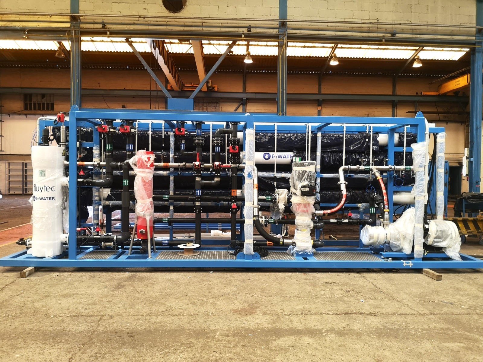
In a large municipal desalination plant, adding a few extra pressure vessels is a minor issue. In a containerized system, internal space inside a 20 ft or 40 ft shipping container is a constrained resource shared with pretreatment, pumps, energy recovery units, electrical panels, CIP systems, and maintenance access. Here, membrane element selection directly impacts mechanical layout.
Switching to higher-active-area elements can eliminate an entire pressure vessel and six membrane elements, yielding substantial savings in footprint, weight, piping, and future replacement costs. However, flux increases slightly and feed spacer thickness drops, making this viable only if pretreatment reliably delivers high-quality feed (stable SDI below 3). If the intake is open and problematic, retaining an extra vessel with 400 ft² fouling-resistant elements is often wiser.
Another design strategy we employ is an internally staged design (hybrid configuration), combining elements of varying permeability within the same pressure vessel. Highly selective, lower-permeability elements are positioned at the lead end where net driving pressure is highest, while high-permeability elements are placed in tail positions where feedwater is most concentrated. This balances flux distribution across the vessel, protects lead elements, and optimizes overall output without increasing system operating pressure.
Managing Boron: When Is a Second Pass Required?
Seawater naturally contains around 4–6 mg/L of boron. At native seawater pH, boron exists predominantly as un-dissociated boric acid—a small, uncharged molecule that passes through reverse osmosis membranes far more easily than ionic salts. A standard SWRO membrane rejects ~90% of boron, which in warm waters can leave permeate concentrations above 1 mg/L. Given that EU Directive 2020/2184 on drinking water specifies a 1.5 mg/L parametric value (2.4 mg/L when desalinated water is the predominant source), membrane selection for drinking water projects must account for this parameter carefully.
When tight boron limits are enforced, two approaches exist: selecting high boron-rejection elements in a single pass, or installing a second pass with brackish water membranes treating part or all of the first-pass permeate, typically dosing sodium hydroxide to raise pH and convert boric acid into borate ions which are rejected efficiently. Because a second pass adds equipment and energy consumption, in containerized plants we always attempt to meet targets via single-pass membrane selection first, incorporating a second pass only when strict final-use requirements demand it.
Pretreatment: No Membrane Survives Poor Pretreatment
The majority of failures in desalination plants stem from inadequate pretreatment rather than membrane flaws. Common causes of seawater fouling include:
- Biofouling: biofilm growth—the primary challenge in open intakes and warm waters.
- Colloids and Organic Matter: particularly during red tides and algal blooms.
- Scaling: calcium carbonate, calcium sulfate, barium sulfate, and strontium sulfate precipitation near the tail end.
- Oxidation: exposure to chlorine or other oxidants causing irreversible polyamide degradation.
Suitable pretreatment for a containerized SWRO plant typically features media filtration or ultrafiltration, 5 µm cartridge filters as a final safety barrier, antiscalant dosing, and, if intake chlorination is used, complete dechlorination with sodium bisulfite upstream of the membranes. The objective is to consistently deliver feed water with an SDI15 under 3 and turbidity below 0.1–0.2 NTU.
Membrane selection and pretreatment design must be planned together: ultrafiltration allows higher active area elements and slightly elevated fluxes, whereas conventional pretreatment on open intakes dictates a more conservative design.
Operation, Cleaning (CIP), and Service Life
To accurately evaluate membrane performance, operating data must be normalized—adjusting parameters for temperature, pressure, and salinity fluctuations over time. Key indicators that a Clean-In-Place (CIP) is required include:
- A 10–15% drop in normalized permeate flow rate.
- A 10–15% increase in normalized salt passage.
- A 15% increase in differential pressure (ΔP) between feed and reject.
Alkaline cleanings remove organic matter and biofouling; acid cleanings dissolve mineral scale and metal hydroxides. Initiating CIP in a timely manner is far more effective than waiting until fouling becomes severe. This is why all I’mWATER containerized plants include integrated CIP systems and continuous monitoring of key parameters.
With proper pretreatment and careful operation, seawater membranes typically last between 5 and 7 years. Poor pretreatment can shorten lifespan to 2–3 years. Elements should be replaced when thorough CIP procedures no longer restore production or rejection levels, or when probing reveals mechanical damage or O-ring leaks.
Checklist for Desalination Membrane Selection
| Question | Why It Matters |
|---|---|
| Do I have a complete seawater analysis (including boron & seasonal temp)? | Foundation for all accurate design projections. |
| What final water quality is required, and for what application? | Dictates membrane family and need for a second pass. |
| What intake type and pretreatment system will be used? | Determines allowable design flux and need for fouling resistance. |
| What is the energy cost and source? | Can justify investing in low-energy elements. |
| How much physical space is available? | In containers, element surface area determines pressure vessel count. |
| Are spare parts locally available? | Critical factor for remote sites or island installations. |
| Have I evaluated total lifecycle costs (TCO)? | Purchase price represents only a fraction of total water production cost. |
How We Do It at I’mWATER
At I’mWATER, we design and manufacture turn-key containerized seawater desalination plants, ranging from small units for hotels, marinas, or isolated communities up to systems producing 3,000 m³/day or more for industrial, mining, or municipal applications. Many of our plants seamlessly integrate with solar PV systems to reduce energy costs and carbon footprint.
For every project, our membrane selection workflow follows these steps:
- Analyze site seawater chemistry and intake conditions.
- Define target permeate water quality and flow requirements with the client.
- Perform projections using manufacturer software across multiple element combinations, seasonal temperatures, and membrane age scenarios.
- Compare alternatives regarding operating pressure, energy usage, water quality, container space, and lifecycle TCO.
- Engineer pretreatment systems tailored to the selected membrane configuration.
Our experience operating across diverse environments—from the Caribbean to the Red Sea and industrial sites across Spain—demonstrates that there is no single “best” membrane in abstract terms: there is only the most suitable membrane for a specific water source, application, and project budget.
Frequently Asked Questions (FAQ)
Can I use brackish water membranes in a seawater plant?
No. They are not engineered to withstand seawater operating pressures, and their salt rejection rate is insufficient. They are only utilized in a second pass treating first-pass permeate.
Is a higher salt rejection membrane always the better choice?
Not necessarily. Higher rejection often requires higher feed pressure and power consumption. If target water quality is satisfied with a low-energy element, it may offer lower operational costs.
Can membranes from different manufacturers be mixed?
While dimensions and connections may be compatible, mixing different brands or models within the same pressure vessel is not recommended (except in planned hybrid configurations), as it disrupts flux balance.
How should membranes be preserved during plant shutdowns?
For short shutdowns, periodic flushes with permeate water suffice. For shutdowns exceeding a few days, membranes must be cleaned and preserved using a biocide solution (typically sodium bisulfite) according to manufacturer instructions.
How often should membranes be replaced?
It depends primarily on pretreatment efficiency and operational discipline. With good practices, membranes last 5 to 7 years. Many plants perform partial annual replacements (10–20% of elements) to maintain steady performance.
Conclusion
Selecting the right seawater desalination membranes requires looking beyond sales catalogues: feed water analysis, temperature variations, target quality, boron levels, available energy, pretreatment design, and—in containerized plants—available footprint must all be considered. A well-planned selection translates to reduced power consumption, fewer cleanings, extended service life, and lower water production costs.
If you are evaluating a containerized seawater desalination plant for your hotel, marina, industrial facility, mining site, or municipality, I’mWATER can help you define the optimal solution—including membrane selection—from water analysis through commissioning. Contact our technical team today to discuss your project.